1. PREPARATION OF THE FERMENTER
1.1 Introduction
The preparation consists of the calibration of the probes and definition of the initial conditions Connect the line cord at the back of the Fermenter and plug it into the power line (90-240 V / 50-60 Hz).
Switch on the Fermenter. The LED on the front panel is yellow. The display shows the last entered parameters.
CONTROL-PANEL
Modes:

- Standby: The Status-LED is yellow and all numbers on the display are still. This is the state of the Fermenter after switching on. The display shows the last entered parameters. In this mode all measurement readings are shown, but the regulation is switched off and the number keys blocked.
- Operation: The regulation is activated by pressing key "R" and the LED is green.
- Calibration: Key "C" starts calibration of pH, pO2, parameter X or setting of address for the PC control (depending on the choice with the cursor). The LED is yellow.
Function keys:
- "R"-Key: Switches between Standby and Operation mode (RUN, REGULATION) of the Fermenter.
- "C"-Key: Switches between Standby (no regulation, LED is yellow) and Calibration mode. During calibration this key memorizes the calibration values.
Arrow Keys:
- Pressing will activate the cursor on the display. The cursor is represented by a blinking field.
- If the cursor is already activated, pressing the arrows will move it to the corresponding direction.
- If a value is being edited (e.g. calibration value) the left arrow clears the value allowing correction, whereas the other arrows save the entered value and move the cursor to the corresponding direction.
The cursor will be deactivated automatically if no manipulation of the number keys or arrows has been effectuated during 15 seconds.
Number Keys:
Are used for setting of numerical values of parameters (if no cursor is displayed the number keys are blocked, preventing inputs by mistake).
Input modification
Place the cursor on the desired parameter. Enter the value with the number keys. The values are entered without decimal point. For example, 9.00 is entered as 900. The left arrow allows correction of the actual value, the other arrows save the entered value.
Input modification is always the same, independently of the operation mode of the Fermenter.
1.2 Probe calibration (gauging pH-probe)
- In standby mode press key "C". Move cursor on the column of the parameter to calibrate. Enter the value of the first gauging solution (e.g. pH 4.00) in the second line (SET VALUE) and press right arrow. The value is displayed in the line below. The probe can now be immersed into the gauging solution. The probe is stirred gently until the measured value (ACTUAL) is stabilised. Then key "C" is pressed again.
- The value of the second gauging solution is entered as described above and the right arrow pressed. The probe is immersed into the gauging solution, gently stirring until the measured value is stabilised. Then key "C" is pressed. An OK message is displayed if the calibration has been performed correctly. Calibration can be interrupted at any moment by pressing key "R". If the calibration is interrupted the values of the former calibration remain unchanged. (For checking purposes the probes are immersed in the gauging solutions and the correct values must be displayed.)
It is important that the sequence as described above is observed exactly! If not, the calibration has not been effectuated properly and has to be repeated.
By pressing key "R" the Fermenter switches to the Standby mode, and anew pressing of key "R" sets the Fermenter to the Operation mode.
MESSAGES
OK - calibration successful
err0 - same gauging solution used twice
err1 - same value entered twice
1.3 Setting the temperature
Move the cursor with the arrows on the field for the temperature setting (SET C, second row, first column). Enter the desired temperature (the value shown on the first line and first column corresponds to the measured temperature and cannot be changed).
Move the cursor on the field of temperature minimum (ALARM LOW). Enter the desired value. If the temperature falls below this value, an alarm is activated and at the exceeded value an asterisk is displayed.
Move the cursor on the field of temperature maximum (ALARM HIGH). Enter the desired value. If the temperature exceeds this value, an alarm is activated and the exceeded value is highlighted on the display.
>> Up
1.4 Setting of the other parameters
The remaining parameters are set analogically to the temperature.
Remarks:
- If the cursor leaves the field (arrows right, up or down) the modified value is automatically saved.
- When the alarm is activated, a continuous 12V signal is present on the alarm output. This is very helpful for directing the alarm to other places, e.g. by phone or activating a sample collection with the aid of the sample collector OMNICOLL. Such samples can contribute to clarification of alarms during unattended fermentation.
- The alarm is deactivated if key "C" is pressed in the calibration mode. The alarm is not activated if the corresponding value of ALARM LOW has been set to 0.0 or 0.00 previously. This prevents alarms of unused functions, e.g. parameter X. (For non zero values alarm is activated).
- For the mixing function (MIX) only the desired value can be entered. The actual value corresponds automatically to the desired value, because the frequency of mixing is controlled precisely through the electronics and deviation thereof is not possible.
1.5 Regulation of pO2
The concentration of dissolved oxygen (pO2) can be regulated by the airflow. This regulation is activated by entering a value for pO2 into the field of the desired pO2 value. The symbol "X" appears on the display at the location of the desired airflow to point out that the airflow is determined by the pO2. The measured airflow value is shown and corresponding alarms (ALARM HIGH, ALARM LOW) can be set. To return to the airflow regulating mode, move the cursor on the field of the airflow and enter the desired value. The symbol "X" is now displayed at the location of the set pO2.
1.6 Calibration of the probes
Calibration of the pH-probe
v. 1. Calibration (Chapter 1.2)
Calibration of the pO2-probe
v. 1. Calibration (Chapter 1.2)
For the 0%-level the gauging solution is a 5% aqueous solution of Na2SO3 (first gauging solution). For the 100%-level, oxygen-saturated water by air is used (second gauging solution).
Calibration of the X-channel
v. 1. Calibration (Chapter 1.2)
Remark:
Temperature probe, flow meter and the mixing frequency cannot be calibrated. Their actual values are guaranteed and controlled electronically.
1.7 START/STOP-Key "R"
START/STOP- or STANDBY-Key "R" activates and deactivates regulation and alarms. The measured values are not influenced thereby and the actual values are displayed. This is helpful during calibration of the probes and the preparation of the Fermenter. In standby mode the LED is yellow. In operation mode it is green.
1.8 PC-Connection
The PC is connected at the back of the Fermenter with a DB 9 connector. The different fermentation parameters can be modified from the PC. A Windows compatible program (FNet) is available. It enables data acquisition and real-time visualisation of the different parameters.
>> Up
2. PREPARATION AND STERILISATION OF THE MINIFOR
2.1 Preparation of the vessel
2.1.1 Mounting of the vibration mixer
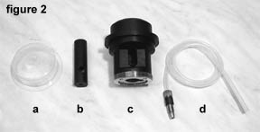
The disassembled head is shown in figure 2.
Place the membrane 2a on the lower side of the cock head and screw the axis of the mixer on the mobile part of the cock head (figure 5).
This membrane guarantees the sterility and must be faultless and well mounted!
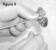
The mixing disc is positioned on the axis, about 1 cm from the end, and tightened by the socket head screw (figure 6). The gas distributor is screwed onto the axis with a socket head screw (figure 7).
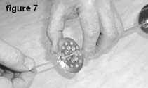
The gassing holes can be cleaned with a wire if necessary.
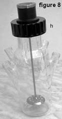
The head is tightly screwed onto the Fermenter vessel with nut 8h (figure 8).
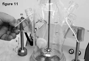
For mounting, it is advantageous to fix the Fermenter vessel onto the housing (figure 11). The lateral holders are adjusted to the right height of the vessel 11k and fixed in position by rotating ring 11l. Elastic O-rings 11m affix the side-necks to the holder.
>> Up
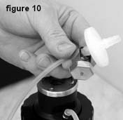
2.1.3 Air outflow
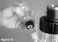
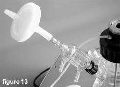
Silicone seal, Teflon washer and screw-hole cap are placed onto the glas air outflow cooler (figure 12).
A silicone tube is fixed onto the outflow cooler on one side and onto the corresponding filter on the other side. The air outflow cooler is now screwed into the side neck of the Fermenter vessel (figure 13).
Alternativelly an electrothermical Peltier cooler can be used. It allows a much better condensation of water vapor because of low temperature attained (about 0 °C). No cooling water is required.
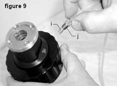
2.2 Cannulae for addition and sample collection
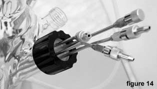
The large silicone plug is screwed, together with a washer, to the larger side neck using the screw-hole cap Pyrex 30. If necessary Luer-Lock end pieces are mounted onto the top of the cannulae (figure 14). The long cannula is preferably used for sample collection, the shorter cannulae are used for addition of pH-adjusting substances and inoculation
2.3 Probes
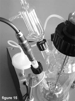
The pH-, pO2- or other probes are connected correspondingly. After calibration they are provided with a silicone plug, Teflon washer and screwed onto the side necks with the aid of a screw-hole cap (figure 15).
Remarks:
Before sterilisation the vessel is filled with medium and all unused side necks are sealed with a silicon stopper, gasket and a cap. The probe connectors have also to be protected with a cap, unless they are of the VarioPin type, which does not need protection.
>> Up
3. START OF THE FERMENTATION
3.1 Connections
The cooled off Fermenter vessel is placed into the ring above the infrared heat emitter and has to be well supported by the lateral holders (figure 11). The lateral holders are fixed in position by rotating ring 11l. Elastic O-rings 11m affix the side-necks to the holder.
- Connect the compressed air of 0.1 MPa (maximum 0.2 MPa) at the connector on the backside. The sterilised air inflow tubing containing the filter is fitted on the air tube at the front on the left. The tubing is affixed by common clamps.
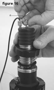
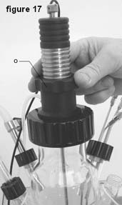
- The electromagnet 16n is screwed, as far as it will go, onto the axis of the cock (figure 16). The cap nut 17 is tightly screwed onto the cock head (figure 17).
- The probes are connected properly to the control unit.
- The sterilised tubing is inserted into the pump heads, the pumps placed onto the racks and connected to the control unit of the Fermenter. The tubings are connected to the supply bottles. The tubing ends are preferably passed by flame to avoid any contamination.
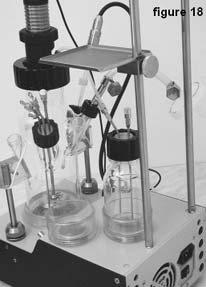
- The supply bottles are placed into the magnetic supports and positioned onto the housing of the Fermenter (figure 18).
- Switch on the pumps, press REMOTE key and choose the direction of rotation. They are still blocked by the microprocessor.
3.2 Start-up of the Fermenter
After a last control of the connections, press key "R". Regulation is now activated.
Once the desired parameter values are reached, inoculation can be performed.
>> Up
4. PRACTICAL HINTS
- Due to the narrowness of the vessel, it is important that it be supported adequately during sterilisation.
- Use the magnetic supports for the supply bottles. The vibrations resulting from the mixer could otherwise start moving them.
- To avoid excessive heating of the airflow regulation valve, it is advised against activating the regulation (LED green) when the Fermenter is not yet connected to the compressed air and a positive air flow has been already selected. The overheating of the regulation gate could damage the valve. An automatic protection will switch off the valve and change the selected air flow to zero. The flow rate has to be programmed again after the air has been connected!
>> Up
5. MAINTENANCE
MINIFOR laboratory Fermenter does not need any special maintenance. Keep the Fermenter clean. Clean it with a humid cloth. Common detergents or ethanol can be used as well.
>> Up
6. SAFETY PRECAUTIONS
If a liquid or saline solution gets into the back side of the Fermenter (power supply), pull out the line cord immediately and contact our customer service.
>> Up
7. TECHNICAL CHARACTERISTICS
Compact microprocessor controlled laboratory Fermenter MINIFOR
Power: |
mains 90-240 V AC / 50-60 Hz, 400 W, CE conform (other voltages on request) |
Dimensions: |
22 x 40 x 38 cm (W x D x H) |
Display: |
LDC 4 x 40 digits with backlight |
Fermenter vessel: |
Pyrex glass with 5 to 8 side necks (culture volumes from 35 ml to 4.5 l) |
Temperature control: |
special radiation heat source with gilded reflector 150 W, |
Regulation: |
from 5 °C over RT to 70 °C |
Measurement: |
from 0 to 99.9 °C in 0.1 °C steps |
Precision: |
0.2 °C (0 to 60 °C) |
Sensor: |
Pt 100 incorporated in the pH sensor |
pH control: |
sterilisable pH electrode pH 0-13, with automatic temperature correction, Variopin connector, two-point semiautomatic calibration |
Resolution: |
0.01 pH unit |
Precision: |
0.02 pH unit |
pO2 control: |
sterilisable Clark type oxygen sensor with fast response and reinforced Teflon membrane, measurement and regulation through regulation of airflow rate, |
Range: |
0 to 25 mg oxygen/l, in 0.1 mg/l steps |
Air flow: |
0 to 5 l/min. in 0.1 l/min. steps, mass flow meter, linearity 3 %, reproducibility 0.5 % |
Control: |
proportional valve using memory metals |
Supplied air pressure: |
between 0.05 and 0.2 MPa |
Agitation: |
40 W Vibromixer 0 to 20 Hz with 1 or more stirring discs; sterility similar to magnetic coupling |
Selectable parameter: |
an additional parameter ("X") can be controlled by the instrument (foaming control, pCO2, optical density, conductivity, weight etc.) |
Sampling ports: |
up to four needles with Luer-Lock or multiseal PEEK fittings can be used for sampling and addition of correction solutions |
Pumps: |
up to 4 independent pumps with speed variation from 0 to 100 % can be used with Minifor (Preciflow, Multiflow or HiFlow) |
Working temperature: |
0-40 C |
Working relative humidity: |
0-90 % |
Weight: |
7.5 kg |
PC control: |
complete PC control and date treatment using FNet program for Fermenters from Sysmatec or SIAM fermentation software |
Inputs and Outputs:
Pump connection (8-pin connector):

Pin no.: |
cable colour code |
1 |
Input remote control + 0/10 V (yellow) |
2 |
Step frequency of pump motor (0 and 12V) (grey) |
3 |
Power supply 0 V (green) |
4 |
Power supply + 12 V (brown) |
5 |
Pump remote control ON/OFF (0 to +12 V) (white) |
6 |
RS485 GND |
7 |
RS485 B (-) |
8 |
RS485 A (+) |
PC-connector: 9-pin
Electrodes: pH and temperature, cable with VarioPin connector
Oxygen: BNC connector
Additional probe: BNC connector (antifoam, pCO2, etc.) Input: 0Ăš10V
Alarm-Output: Audio connector 12 V/0.1 A
>> Up
8. ACCESSORIES (OPTIONAL)
- Connector for controlling sample collector OMNICOLL and its pump (Art. No.: 6911)
- Preciflow pump (Art. No. 4801), Multiflow pump (Art. No.: 4901), HiFlow pump (Art. No.: 5001)
- Pump connection cable (Art. No.: 6910)
- Peltier element for outflow cooling
- Oxygen electrode
- Spare parts on request
>> Up
9. WARRANTY
12 months on material defects or manufacturing defectives, if the device was used according to the operation manual. Condition for reparation is delivery to our repair service with a detailed description of the failure. Transport costs and risks are for the customer's account.
>> Up
MASSFLOW - operating instructions
1. SET UP
1.1 POWER SUPPLY

The Massflow has a low consumption of electric current and is normally connected to the 12 V DC line of the MINIFOR using the supplied 8-pole cable with DIN connectors. One connector is plugged into the rear of the Massflow (REMOTE), the other to any of the four pump sockets at the rear of the Minifor laboratory Fermenter.
When used independently without a Fermenter, a universal plug integrated power supply 90-240 V AC / 50-60 Hz, 12 V, 6 W DC power supply can be supplied (cat. no. 4815). The power supply cable is connected to the three-pole socket (POWER) at the rear of the Massflow.
When the Massflow is connected to a power supply, all LEDs and the display are lit up for one second. This allows a function control of all signal elements.
1.2 GAS INPUT AND OUTPUT

Gas tubing (interior diameter about 5.5 to 6 mm) is connected to a nozzle (gas in) and secured in place with appropriate clamps. The maximum permissible gas pressure is 0.2 MPa (2 atm or 30 psig). Higher pressures will damage the instrument! A simple overpressure security valve is part of the inlet nozzle, which allows the gas to escape when the pressure exceeds about 0.22 MPa.
Fix the other tubing onto the gas output nozzle. Turn on the gas supply. The regulating valve is closed and no gas will come out of the output.
1.3 SETTING THE FLOW RATE
Press the SET button. The corresponding LED will light up and the display will show the preset value of the flow rate. Set a desired flow rate with the buttons underneath the display. Press the SET button again. The LED is switched off and the display shows the actual flow rate. It should indicate 0.0 l/min. Press the ON/OFF button. The corresponding LED is lit up. After about 10 seconds (about 30 seconds for low flow rates) the flow rate will progressively attain the preset value.
>> Up
2. REMOTE CONTROL
2.1 ANALOGICAL CONTROL
ON/OFF
The gas flow rate can be switched off by applying a voltage (3-12 V) to contact no. 5 of the eight-pole socket (figure 1) at the rear of the MASSFLOW (0 V is connected to pole no. 3). The 12 V voltage can also be taken from contact no. 4 of the socket). The applied voltage will stop the gas flow. When this voltage disappears the gas flow will continue until it is switched off by using the ON/OFF button.
PROPORTIONAL FLOW RATE CONTROL
The gas flow rate can be regulated over the whole range of 0.0 to 5.0 l/min by an external DC voltage 0 to 10 V applied to contact no. 1 of the rear side socket (REMOTE). The 0V line must be connected to contact no. 3 of the same socket (figure 1). The remote control is activated by pressing the REMOTE button. The corresponding REMOTE LED is lit.
2.2 PC CONTROL
A PC can be used to regulate all functions of Massflow over an RS-485 line. The commands used for all functions are indicated below. The line should be connected according to figure 1. (A resistor of 100 ohms should be connected between both RS-485 lines, if it is not already present. This resistor is not part of Massflow or any other Lambda instrument.) When the digital control is activated the REMOTE LED is on and all manual commands (with exception of the SET button) are blocked.
ADDRESS SETTING FOR PC CONTROL
The digital control requires an attribution of an appropriate address to the Massflow. This is done in the following way: Pull out the power supply cable from the rear of the Massflow. Press and hold the SET button while plugging the cable into the socket again. The front panel illuminates and the display shows A00. Release the SET button. Select a desired address from 0 to 99 and press the ON/OFF button to store it in the memory.
>> Up
3. PROGRAMMING OF FLOW RATES
Up to 50 pairs of flow rates and time periods can be programmed. This allows almost any flow rate profile to be obtained. To enter the programming sequence press the REMOTE and RUN buttons simultaneously until the message PGM appears on the display. (The ON/OFF button is used to go from one step of the program to another and at the same time stores the previous step in the memory.) Press the ON/OFF button. The message F01 will appear for one second on the display followed by the value of the flow rate for the first step, which has been stored in the memory. If the Massflow is new or the previous program has been deleted the value 0.0 will be displayed.
Press the buttons under the display window to select the flow rate value for the first step (for example 1.0).
Press the ON/OFF button again. The message t01 will appear on the display indicating that the time period of the first step can be programmed. The display will then show the time period stored earlier for the first step.
Select the duration of the first flow rate (for example 02 = two minutes) and press the ON/OFF button to store the duration in the memory and go on to the next step. F02 will appear on the display and after one second the value of the flow rate in the memory will be displayed.
Select the value of the flow rate for the second step and press the ON/OFF button to store your setting and continue on to the setting of the duration for the second step. The message t02 will shortly appear on the display followed by the duration, which has been stored earlier.
Select the duration and store it by pressing the ON/OFF button. F03 will appear on the display and you can proceed as described in the first two steps. All other steps are also programmed in this way.
When the duration of the last step has been entered the programming is terminated by pressing the REMOTE and RUN buttons simultaneously until the message End appears on the display.
The program is started by pressing the RUN button and the corresponding LED will light up. The flow rate of the first step will appear on the display if the SET button is activated. Otherwise, the reading 0.0 seen at the beginning will increase progressively until the programmed flow rate is attained. This may take about 15 seconds depending upon the selected flow rate.
During the execution of the program it is possible to manually modify the flow rate or even stop the flow rate with the ON/OFF button. However, the program will continue when the next step is executed. This allows certain emergency manipulations to be performed without terminating the program.
The running program can be terminated definitively by pressing the RUN button. The corresponding LED will go out. After the last step of the program the gas flow will be stopped.
If you wish to maintain a certain flow rate at the end of the program, set the duration of the last step to 00. Such time is not defined and the flow rate will be maintained until the Massflow is switched off manually or the power supply is disconnected.
READING THE PROGRAM
Reading the program can be done in the same way as the programming described above. No modification is made by the buttons under the display. After the last step a simultaneous pressing of the REMOTE and RUN buttons will end the reading process. The message END will appear on the display. Pressing the RUN button will start the program.
DELETING THE PROGRAM
Press the REMOTE and RUN buttons simultaneously. The message PGM will appear on the display. Press both buttons again simultaneously. The message CLE will appear on the display. This indicates that the program has been deleted from the memory.
>> Up
4. VOLUME TOTALIZER
The Massflow generates an electric signal after a delivery of each 5 ml of gas. This signal can be integrated and transformed into a DC voltage using a Pump-Flow Integrator (cat.no. 4803). A full range volume of the integrator can be adjusted from 10 l to 5 000 l. After this an automatic reset will set the integrator to zero and the integration will continue. In connection with a PC any volume from 5 ml upwards can be recorded (FNet or SIAM).
>> Up
5. USE OF MASSFLOW FOR PH CONTROL DURING CELL CULTURE
The pH of a cell culture media is kept constant by the controlled addition of gaseous carbon dioxide (CO2). The Massflow is ideal for this purpose.
Connect the CO2 gas tubing to the Massflow and to the bioreactor. Plug the remote control cable of the Massflow into the pump socket (ACID) on the rear side of the Minifor.
Press the REMOTE button on the Massflow and switch the flow on with the ON/OFF button. The pH of the medium will be controlled automatically.
Note: If the actual pH of the medium is much higher than the preset value on the Minifor, the initial flow of carbon dioxide may be very high. To prevent this, it is advisable to start with manual control of CO2 addition until both the actual and preset pH values are almost identical. Only then should the REMOTE button be pressed and the automatic control started.
If the pH of the culture medium is lower than the preset pH. The excess of CO2 has to be removed. In most cases this is achieved by air, if the air is used for control of dissolved oxygen. When this is not possible a second Massflow connected to nitrogen and its remote control cable plugged into the pump socket (BASE) in the rear of the Minifor is required.
When the actual pH is lower than the preset pH, the flow of nitrogen controlled by the second Massflow will blow the excessive amount of carbon dioxide out and the pH will increase.
As mentioned above, when there is a big difference between the actual and preset pH, it is advisable to initially control manually and only later activate the remote control by pressing the REMOTE button.
The best way to connect both gases to the MINIFOR is by using T, Y or X tubing between the regulated air output of the Minifor and a sterile gas filter on the gas line leading to the bioreactor vessel.
The use of one or two Massflow gas flow rate controllers together with the MINIFOR bioreactor assures a good pH and pO2 control during cell culture. It may completely replace expensive gas mix stations and assure much better parameters.
>> Up
6. CONNECTIONS:
INPUTS / OUTPUTS:
Contact no.: |
socket and cable colour code |
1 |
+ input remote gas flow control 0-10 V (yellow)* |
2 |
5 ml signal from Massflow (0 and 5 V) (grey) |
3 |
ground, 0 V (green) |
4 |
+ 12 V (brown) |
5 |
+ input remote ON/OFF (white)* 0 V = ON, 3-12 V = OFF * (zero line connected to contact no. 3) |
6 |
GND RS-485 pink conductor |
7 |
RS-485 B (-) red conductor |
8 |
RS-485 A (+) blue conductor |
>> Up
7. ACCESSORIES AND SPARE PARTS
Pump/gas-Flow Integrator (cat. no. 4803)
The Flow Integrator allows the simple but precise integration of the amount of gas, which has passed through the MASSFLOW gas controller. The electric pulses, which correspond to 5 ml of gas (air, nitrogen, oxygen) are registered and transformed into a direct voltage. The resulting voltage can be measured or recorded by common recorders or voltmeters. Using an RS-485 line, the gas volume can be recorded on a PC (for example using the fermentation software FNet).
In processes where the gas flow is controlled e.g. by a pH-stat during a cell culture to keep the pH of the medium constant, it is often important to know when and how much acid (such as carbon dioxide) or base (nitrogen in cell cultures) was added. This data yields important information about the process, its kinetics, time of completion etc.
Another use of the INTEGRATOR is the measurement of enzyme activities (esterases, amidases, lactamases and other enzymes).
The Pump/Gas-Flow Integrator is connected by a cable to the 8-pole socket at the rear of the pump (see picture).
Remote control cable (cat. no. 4810)
Power supply 90-240 V AC / 50-60 Hz, 12 V, 6W DC (cat. no. 4815)
>> Up
8. GUARANTEE
Lambda offers a three-year parts and labour guarantee on all its products, when the instrument has been used in accordance with our operating instructions and the advice given above.
CONDITIONS OF GUARANTEE:
- The instrument must be returned with a complete description of the defect or problem.
- The customer should send the instrument to our service office.
- Lambda will not be responsible for any damage or loss, which may occur during transportation.
- Failure to fulfill these requirements will invalidate the guarantee.
|